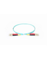
UPC or APC, which connector should I choose?
Choosing the appropriate type of polishing for optical connectors is crucial in network planning and should not be random.
First, let's take a closer look at the structure of the optical fiber:
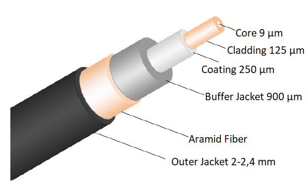
Internal structue of an optical fiber
The fiber is made of a special type of quartz glass. Its main part is the core, covered with a cladding and protective layer. The operation of the optical fiber relies on the use of two materials that conduct light with different refractive indices. The refractive index in the core is slightly higher than in the cladding.
Optical fibers can be connected in two ways: either using a mechanical connecto or by using a fusion splicer. The operation of almost all currently used fiber optic connectors is based on the same principle, which involves securing the fiber in a precisely drilled cylindrical ferrule. The connection is made by centering the ferrules of both connectors in the sleeve of the fiber optic socket. There are various types of mounting solutions, including threaded, bayonet, and snap-in types. To ensure the repeatability of parameters and the reliability of connections, perfect centricity of fiber cores in ferrules is required. This places tight requirements on the tolerances of dimensions in ferrule production.
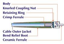
Structure of a fiber optic connector
Why polishing matters?
The most commonly used types of fiber optic connectors, such as LC, SC, ST, FC, E2000, come in two types of ferrule end-face polishing: UPC (Ultra Physical Contact) and APC (Angled Physical Contact). The type of polish is indicated by the color code of the connector: blue for PC-UPC, black for FC/PC-UPC, green for APC.
The geometry of connector joints focuses on ensuring proper physical contact between two fibers placed in a ferrule. The spherical surface of the fibers is precisely polished so that the contacting surfaces meet centrally in the axial sleeve. The elimination of the air gap is achieved by a gentle pressure of the fibers being joined (the fibers bend until they contact the sleeve). The physical contact between the fibers must be durable and maintained over time regardless of changes in temperature, pressure, or vibration. The proper pressure of fibers is provided by the spring of the connector, ensuring physical contact regardless of environmental changes.
International standards specify three key physical parameters that allow to determine the quality of polished surfaces: the radius of curvature (radius of the sphere formed on the polished axial sleeve), fiber height (distance of fiber protrusion or cut after polishing in relation to the axial sleeve), and highest peak displacement (polishing and vertex displacement, eccentricity of vertex and polishing).
The fiber optic ferrule is appropriately polished to improve the performance of fiber optic connections made using optical connectors.
To minimize losses, fiber optic connectors usually contact end surfaces properly polished, used in the UPC optical joining technique or at a slight angle in the APC angle joining technique to eliminate reflections. However, UPC connectors are not perfectly flat and have a slight curvature - for better core alignment.
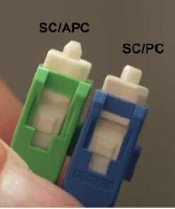
Photo of SC/APC and SC/PC connectors
How does the difference in polishing affect performance?
In UPC connectors, light is reflected straight towards the light source, while the 8-degree angled connector end in APC reflects light towards the cladding. This causes some differences in the return loss, which is a measure of reflected light expressed as a negative dB value (the higher the value, the better). Standards recommend that the UPC connector return loss should be -50 dB or more (corresponding to a nominal reflection coefficient of 0.001%) and the APC connector return loss should be -60 dB or more (corresponding to a nominal reflection coefficient of 0.0001%).
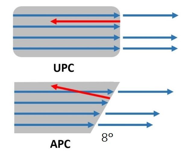
Difference between UPC and APC polishing
Difference between the described connectors:
- In an APC connector, light is not reflected back to the source, but is absorbed by the fiber coating;
- In a UPC (and PC) connector, light is reflected back to the source.
The return loss is different from the insertion loss, which refers to the amount of optical energy lost by the connector or cable length. Insertion loss is used to determine loss budgets. Achieving low insertion loss is usually easier with UPC connectors due to smaller air gaps than in APC connectors. Production techniques have greatly improved to obtain more precise angles on APC connectors and approach insertion losses similar to those of UPC connectors.
Application
It is the specific need that should influence whether we choose UPC or APC polishing.
APC: In fiber optic telecommunication systems with data rates above 600 Mb/s, the use of connectors with an APC polish is recommended. Systems that are more sensitive to return losses also require the use of APC connectors. For example, systems operating in higher optical wavelength ranges above 1500 nm, used for RF video signals, in which reflected light can adversely affect the signal. This is why APC connectors are chosen in FTTX applications. APC connectors are also commonly used in passive PON networks, as many of them use RF signals to deliver television.
UPC: In applications where cost and simplicity are more important than optical performance, UPC connectors are used.
Can APC and UPC connectors be linked together?
It should be remembered that APC and UPC connectors cannot and should not be connected to each other!
Not only because of lower performance due to the misalignment of fiber cores, but also because of the danger of damaging both connectors (losses can reach even 10 dB). When choosing the type of connector, it is worth noting that higher performance connectors offer savings in valuable dB, so for applications requiring precise fiber optic signaling, APC should be the first choice, while less sensitive systems will work just as well using UPC.
Don't want to miss the next articles? Subscribe to our newsletter or follow us on:


