My Cart
You have no items in your shopping cart.
It turns out that the optical module we wanted to connect isn't establishing a link – it’s not working. What could have gone 'wrong'? And more importantly – how do we check it? Problems with optical modules can generally be divided into three categories:
No technology is completely fault-proof, which is why it's essential to know how to diagnose optical modules and troubleshoot connection problems.
Suspecting an incompatibility issue between the optical module and the network device? Watch for error messages like "unsupported transceiver" or "unknown transceiver," or check if the module works fine on a different device. Always test the module in another port or device to rule out port-specific problems. If the issue persists, start by consulting the technical documentation of the network device to confirm if the module type is supported. Verify that the port's speed and protocol are compatible with the optical module. If everything matches, check the device's firmware and update it to the latest version if necessary.
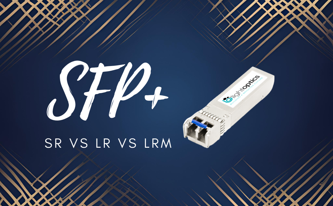
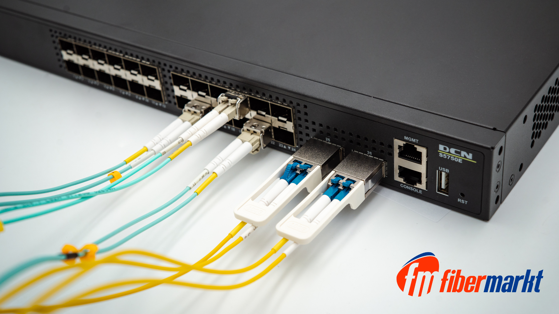
If the module doesn't work and there are no clear signs of incompatibility, the problem could lie in connection settings or physical aspects. For example, the port might be set to 1 Gbps, while the module is SFP+ 10 Gbps, or there might be damage to the fiber optic cable. Inspecting fiber quality can be done in several ways, such as using an optical microscope for checking cleanliness and an Optical Time-Domain Reflectometer (OTDR) to assess signal quality.
What if the problem "follows the module"? To verify module damage, use the Digital Diagnostics Monitoring (DDM) function built into optical modules. DDM is the most effective tool for diagnosing optical modules. It is available in most modern optical modules, including those from LightOptics. It allows real-time monitoring of key parameters, such as:
You can invoke the DDM function, for example, with the command # show transceiver detail in CLI.
Compare all readings to the values in the optical module's technical documentation to identify deviations from the norm. Additionally, check that DDM readings remain stable during transmission. Sudden fluctuations, like spikes in laser current, can indicate unstable and faulty operation.
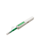
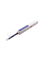
If the issue lies in low input power readings (Rx Power), dirt contamination might be the culprit. Clean the module and fiber optic ends. Just as a dirty window limits the amount of light entering a room, a contaminated optical module or fiber will hinder the laser signal from reaching the photodiode. In severe cases, this could be perceived as a lack of signal by the switch. If cleaning doesn’t help, inspect the connection route for potential damage.
In other cases, if the readings indicate the previously mentioned errors, replacing the optical module might be necessary.
Every device has its unique characteristics and challenges; there is no perfect product. Regularly monitoring the condition of both the optical modules in the system and the fiber optic connection is essential. The DDM function in optical modules allows real-time control over parameters such as output power, laser current, and temperature, helping to quickly identify physical damages like a burned-out laser.
All modules and AOC and DAC cables in the Fibermarkt store come with a 2-year warranty. We offer technical support before and after purchase. Contact us via phone, email, or chat on our website.
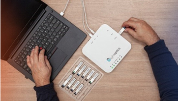
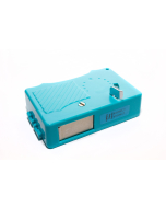
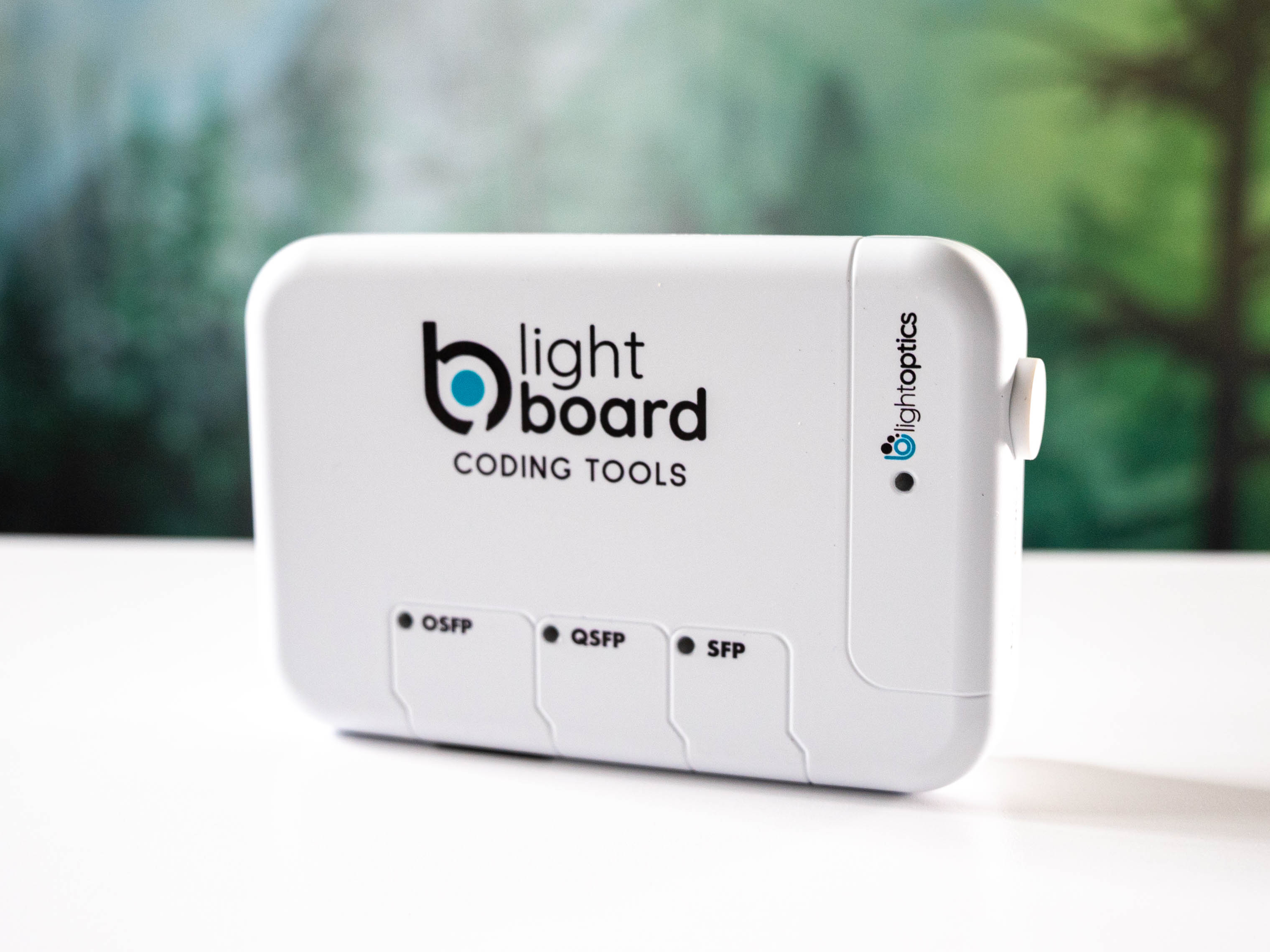
This device allows you to adjust the coding of any module. See how!
.

The link doesn't go up? Try these tips.

Monitoring the performance of an optical module has never been so easy.