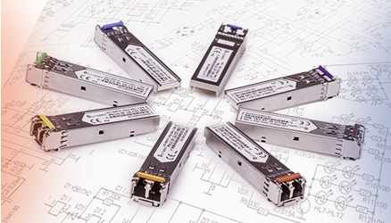








You are wiring a new GPU server or small AI cluster and need a 100G connection for the GPU server. The switch ports are QSFP28, but you still must choose between DAC, AOC, QSFP28 SR4, CWDM4 or LR4 — and the “right” choice depends on distance, cabling plant, power, and how the host behaves with each medium.
In short: use a short passive DAC where the server and switch are in the same rack and you control both ends; choose AOC if you need up to a few dozen metres with low weight; use QSFP28 SR4 over MPO multimode for structured intra-row cabling; and use CWDM4 or LR4 with duplex LC over single‑mode when you need 100G beyond the row or across rooms and buildings. Modern AI reference designs often use 200/400GbE for the core compute fabric, but 100GbE remains very effective for server access, storage, uplinks, and staged migrations.
The sections below walk through each option, how it behaves electrically and optically, what to verify for compatibility, and which choice makes most sense for typical GPU, storage and uplink scenarios.
Quick answer: how to choose a 100G link for your GPU server
Use this as a starting decision tree before diving into details:
- Same rack, < 3–5 m, controlled environment → start with passive QSFP28 DAC.
- Same or adjacent rack, 5–30 m, need slim/light cabling → consider QSFP28 AOC.
- Structured multimode cabling with MPO/MTP, up to ~70 m OM3 / 100 m OM4 → use 100GBASE‑SR4 QSFP28.
- Single‑mode plant, up to 2 km → choose 100G CWDM4 QSFP28.
- Single‑mode, up to 10 km campus/metro → choose 100GBASE‑LR4 QSFP28.
All of these rely on QSFP28 ports (four 25G electrical lanes), but that does not guarantee compatibility. Always verify coding, firmware, FEC, breakout configuration, connector type, fibre type and link budget for your specific switches and servers.
Quick option overview for 100G GPU links
If you already know your distance and cabling type, you can scan the detailed comparison table below and then jump directly to the section for DAC, AOC, SR4, CWDM4 or LR4 for buying criteria and compatibility checks.
Start with the port, distance and installed cabling.
Compare 100G QSFP28 options
QSFP28 100G options at a glance
The following table compares the main 100G options for GPU servers. The second column is highlighted as the lowest complexity option in common same‑rack deployments, not as a universal recommendation.
For a broader view of compatible optics and cables, see the QSFP28 100G transceiver range at Fibermarkt and 100G QSFP28 DAC cables.
| Criterion | DAC LOWEST COMPLEXITY* | AOC | SR4 | CWDM4 | LR4 |
|---|---|---|---|---|---|
| Typical use | Same‑rack server‑to‑switch or storage, lab wiring | Rack/row server‑to‑switch where DAC is too short/heavy | Intra‑row links over MPO multimode panels | Short‑reach single‑mode between rooms / small sites | Campus / metro single‑mode, data hall to core |
| Medium type | Passive copper twinax | Fixed active optical cable | Parallel multimode fibre (MPO/MTP) | Single‑mode fibre, duplex LC, coarse WDM | Single‑mode fibre, duplex LC, LAN‑WDM |
| Connectors at port | QSFP28 direct attach cable | QSFP28 active optical cable | MPO/MTP 12‑fibre to QSFP28 | LC duplex to QSFP28 | LC duplex to QSFP28 |
| Typical distance range | ~1–5 m (product and host dependent) | ~3–30+ m (product dependent) | Up to 70 m on OM3, 100 m on OM4 (standards‑based) | Up to 2 km (CWDM4 MSA class) | Up to 10 km (100GBASE‑LR4) |
| Re‑use of existing cabling | No (fixed cable assembly) | No (fixed optical cable) | Yes, if MPO multimode backbone exists | Yes, on SMF with LC connectors | Yes, on SMF with LC connectors |
| Installation complexity | Very low: plug and play | Low: plug and play, manage bend radius | Medium: MPO polarity, trunk/cassette planning | Medium: single‑mode patch routing, link budget check | Medium–high: longer‑reach optics planning, link budget |
| Flexibility to change optics later | Low (cable is integrated) | Low (cable is integrated) | High (replaceable transceivers, reuse fibre) | High (replaceable transceivers, reuse fibre) | High (replaceable transceivers, reuse fibre) |
| Fibre type | Not applicable (copper) | Vendor‑specific multimode fibre inside cable | OM3/OM4 multimode | OS1/OS2 single‑mode | OS1/OS2 single‑mode |
| Common AI/ML role | Access link for GPU servers in same rack | Access link when racks are spread across row | Row‑level aggregation for GPU/storage pods | Short DC‑to‑DC or DC‑to‑core links | Campus WAN / DC interconnect, core integration |
*“Lowest complexity” assumes compatible host ports within a single rack. It does not imply that DAC is always the optimal choice.
Option 1: 100GBASE‑CR4 DAC – simplest for same‑rack GPU links
Passive QSFP28 DAC (100GBASE‑CR4) is usually the most straightforward 100G connection for a GPU server when the server and switch are very close.
In the Cisco portfolio, passive 100G DAC variants commonly cover 1–5 m, with actual reach and required FEC depending on both the cable and the host platform. Other vendors offer similar ranges. That makes DAC ideal when server and top‑of‑rack (ToR) switch are in the same rack or immediately adjacent racks.
When to choose DAC for a GPU server
- Distance is comfortably within the supported DAC length for both hosts (typically ≤ 3–5 m).
- Server and switch are in the same rack or on the same rack row with short cable routing.
- You want minimal optical complexity: no cleaning, no fibre polarity issues.
- You fully control both ends and can validate coding / qualification for your hardware vendors.
Points to verify before deploying DAC
- Host support for passive DAC length and gauge, and whether RS‑FEC is required for a given length.
- Vendor coding and firmware acceptance on NICs, DPUs, and switch ports.
- Thermal and airflow impact of thicker copper bundles, especially in dense GPU chassis.
- Mechanical strain relief so the heavier DAC does not stress QSFP28 cages on tall racks.
DACs are an excellent default for short 100G GPU access links, but they do not scale well across rows or when rack layouts change frequently. Where the distance or the cabling density is an issue, AOC often becomes more attractive.
Both endpoints are in the same rack?
Check 100G QSFP28 DAC cables
Option 2: 100G QSFP28 AOC – lightweight row‑scale connectivity
Active Optical Cables (AOC) embed optics within a fixed QSFP28‑to‑QSFP28 assembly. Inside the cable is optical fibre, not copper, and electronics in the QSFP28 shells convert electrical to optical and back.
AOCs are lighter and can reach farther than passive DAC in typical rack/row deployments. They are flexible, have smaller bend radius requirements than thick copper, and can simplify cable routing in dense GPU racks.
However, an AOC is a fixed assembly: the optical ends are not field‑detachable. You cannot repatch to existing patch panels or repurpose the fibre for another application later.
You can review a typical AOC variant here: QSFP28 to QSFP28 100G Active Optical Cable 3 m.
When to choose AOC
- You need to reach further than passive DAC length limitations, across or between racks in the same row.
- You want to minimise cable weight and thickness for better airflow and cable management.
- You do not need to patch through existing optical panels or reuse fibre later for other protocols.
Things to check for AOC
- Host platform support for the specific AOC model and coding.
- Maximum supported AOC length for the NIC and switch.
- Minimum bend radius along the routing path.
AOCs can give you the simplicity of DAC with the handling advantages of fibre, and they work well in small AI clusters where racks are spread across a row with consistent port mappings.
Option 3: 100GBASE‑SR4 – MPO multimode for short‑range structured cabling
100GBASE‑SR4 uses parallel optics over multimode fibre, typically OM3 or OM4, with an MPO/MTP connector at the QSFP28. It runs four 25G optical lanes in each direction, matching the four 25G electrical lanes in the QSFP28 interface.
According to Cisco’s 100G QSFP data sheet, 100GBASE‑SR4 supports up to 70 m on OM3 and 100 m on OM4 multimode fibre. These are standards‑based optical reaches; individual products may specify additional parameters such as minimum and maximum losses or required FEC.
An example product is the Fibermarkt QSFP28 100GBASE‑SR4 850 nm MPO multimode transceiver.
Key considerations for 100GBASE‑SR4
- MPO vs LC: SR4 requires MPO/MTP connectors and is not directly interchangeable with duplex LC. You need appropriate patch panels, cassettes or fanout cables.
- Polarity: correct MPO polarity (Type A/B/C) is critical. Incorrect polarity will lead to lane mis‑mapping and link failures.
- Fibre type: OM3 or OM4 with verified insertion loss and return loss within the SR4 budget.
- Cleaning: MPO connectors are sensitive to contamination. Routines for inspection and cleaning are important in production.
When to choose SR4 for GPU servers
- You have or plan a structured MPO‑based multimode backbone within a row or pod.
- You need to reach distances beyond DAC/AOC but still within a single data hall (up to ~100 m on OM4).
- You value the ability to reuse the multimode backbone later with different optics or speeds (e.g., future multimode standards).
SR4 is often a good fit for GPU pods with patch‑panel based cabling in the same row or neighbouring rows, such as connecting a GPU rack to a row aggregation switch through MPO panels.
Your link uses OM3/OM4 and MPO/MTP?
View the 100G QSFP28 SR4 option
Option 4: 100G CWDM4 – cost‑effective single‑mode up to 2 km
100G CWDM4 uses four wavelengths over single‑mode fibre, multiplexed on a single duplex LC pair. It is designed for short‑reach single‑mode up to approximately 2 km for the commonly referenced CWDM4 MSA class.
In many modern data centres, CWDM4 is a practical way to carry 100G between rooms, across a campus building, or to a nearby secondary site using a simple SMF plant.
You can see a representative module here: QSFP28 100G CWDM4 LC single‑mode transceiver up to 2 km.
When to choose CWDM4
- You have single‑mode LC cabling and need to go further than SR4 allows but not beyond 2 km.
- You want simpler link budgets than DWDM systems, without amplifiers or dispersion compensation for short metro distances.
- You plan a staged migration where 100G will later coexist with 200/400GbE over the same SMF plant.
Points to plan for CWDM4
- Ensure that link loss (connectors, splices, patch panels) is within the CWDM4 optical budget.
- Check whether FEC policies on NICs/switches align with the CWDM4 spec used by your modules.
- Reserve wavelength plans if you intend to introduce additional WDM services on the same fibre later.
CWDM4 is often chosen for 100G uplinks from GPU racks to aggregation or core switches in another room or building, where single‑mode fibre is already present.
Option 5: 100GBASE‑LR4 – 10 km single‑mode for campus and DCI
100GBASE‑LR4 is the long‑reach single‑mode standard for 100GbE. It also uses four wavelengths over a duplex LC link, but with a tighter wavelength spacing and link budget targeted at distances up to 10 km over OS1/OS2 single‑mode fibre.
A typical example is the Fibermarkt QSFP28 100GBASE‑LR4 1310 nm LC single‑mode transceiver.
When to choose LR4
- You need to connect your GPU server fabric to a core or aggregation switch in another building or campus, up to about 10 km.
- You are implementing data centre interconnect (DCI) where 100G is adequate for the application.
- You want a standards‑based interface commonly supported across switch and router vendors.
LR4 planning points
- Validate the optical link budget carefully for longer runs, including splices and patch panels.
- Check your fibre type (OS1 vs OS2) and any existing passive components that may affect dispersion and loss.
- Consider future 400G migration; you may later prefer to reserve specific fibres for higher‑rate DWDM or 400G LR interfaces.
LR4 is typically not the first choice for simple GPU access links, but it becomes relevant when a GPU or storage cluster spans multiple sites or needs 100G backhaul to a separate core.
100G for AI and GPU workloads: where 100G still fits
AI and accelerated networking documentation from NVIDIA shows current enterprise reference designs using 400GbE for dense east‑west compute fabrics, with 100/200GbE still used for:
- Server access and management for GPU and CPU hosts.
- Storage access where underlying arrays or file systems do not saturate 400G yet.
- Uplinks from ToR leaf switches to aggregation or core switches.
- Stepwise upgrades from existing 10/40G environments.
For a single GPU server, a small AI lab cluster or an incremental upgrade, a well‑planned 100G connection for the GPU server is usually cost‑effective and operationally simple, especially if it integrates with an existing 25/50/100G leaf‑spine design.
Compatibility checklist for 100G QSFP28 GPU links
Form factor alone never guarantees interoperability. QSFP28 normally carries four 25G electrical lanes for 100GbE, but not every port supports every optic type, DAC length, breakout or standard. Before ordering, run through this checklist:
1. Host and port capabilities
- Confirm the port supports 100G operation with the intended media type (CR4, SR4, CWDM4, LR4, AOC).
- Check whether the port expects IEEE 802.3 100G standards, specific MSA variants, or vendor‑specific profiles.
- Verify if breakout modes (e.g., 4×25G, 2×50G) are enabled or disabled; not all 100G ports support them.
2. Coding, vendor lock‑in and firmware
- Check if NICs and switches allow third‑party coded modules and cables, or require exact vendor part numbers.
- Confirm the firmware version on switches/servers; some platform releases add or remove compatibility with specific optics or DAC/AOC SKUs.
3. FEC and signal integrity
- Determine whether RS‑FEC or other FEC is required or recommended for:
- Longer DAC lengths and higher gauge copper.
- Specific optical reaches (especially on marginal links).
- Confirm FEC settings on both ends match and are supported by your chosen optics or cables.
4. Physical media and connectors
- For SR4:
- Check MPO/MTP type (e.g., 12‑fibre, pinned/unpinned) and polarity.
- Ensure the backbone fibre is OM3 or OM4 with reach within 70 m (OM3) or 100 m (OM4) per Cisco’s SR4 specs.
- For CWDM4/LR4:
- Ensure OS1/OS2 single‑mode with duplex LC connectors.
- Calculate total link loss and compare against the module’s optical budget.
- For DAC/AOC:
- Validate supported cable gauges and lengths for the specific NIC and switch.
- Check mechanical routing and strain relief for tight spaces in GPU servers.
5. Environmental and operational factors
- Ambient temperature around GPU servers can be high; ensure selected modules or DAC/AOC meet temperature ratings for that zone.
- Plan for maintenance scenarios: can an optic or AOC be replaced without disturbing multiple GPU nodes at once?
Four common deployment scenarios and recommended 100G link types
Scenario 1: Single GPU server and ToR switch in the same rack
Topology: One or a few GPU servers connected to a top‑of‑rack 100G switch, cable length 1–3 m.
Recommended link type: Passive QSFP28 DAC
- Minimises cost and complexity.
- Easy to deploy and replace without touching optical cabling.
- Ideal for lab environments and small AI PoCs.
You can explore length options in the Fibermarkt 100G QSFP28 DAC cable selection.
Scenario 2: Small AI cluster across two or three racks in the same row
Topology: 4–16 GPU servers in adjacent racks, connected to a leaf switch at one end of the row; cable lengths 5–20 m.
Recommended link type: AOC or SR4, depending on cabling plant.
- If you use direct point‑to‑point cabling between servers and a leaf, AOC is simple and clean.
- If your row has MPO‑based patch panels between racks, 100GBASE‑SR4 lets you use structured cabling.
AOCs can be selected by length from the QSFP28 100G AOC product family (3 m variant shown).
Scenario 3: GPU rack uplink to aggregation switch in another room
Topology: One or more GPU racks uplink to an aggregation/core switch in a separate room within the same building, distances between 100 m and 2 km on single‑mode fibre.
Recommended link type: 100G CWDM4
- Uses existing single‑mode LC cabling without the reach overhead of LR4.
- Simplifies planning for short data centre inter‑room or building links.
- Well suited as a 100G uplink from ToR switches serving GPU and storage nodes.
The Fibermarkt 100G CWDM4 LC SMF module is representative of this class.
Scenario 4: Edge GPU node connected to central fabric across campus
Topology: A GPU server or small accelerator pod located in a satellite data room or building, connected back to the main network core over campus fibre, distances up to 10 km.
Recommended link type: 100GBASE‑LR4
- Provides a standards‑based 10 km reach on OS1/OS2 SMF.
- Works well for campus or metro access where 100G capacity is sufficient.
- Allows gradual evolution toward higher‑rate DCI or 400G links on separate fibres.
Consider a 100GBASE‑LR4 QSFP28 transceiver such as the Fibermarkt 10 km LR4 module for these use cases.
Putting it together: selecting your 100G GPU server link
To convert the above into a concrete choice, walk through these steps:
- Measure realistic distance (including patch panel hops and routing slack).
- Document existing cabling type (copper, OM3/OM4 MPO, SMF LC, dark fibre availability).
- Check host capabilities and qualification matrices for optics, DAC and AOC.
- Choose the lowest‑complexity medium that satisfies:
- Distance + link budget.
- Cable management and airflow for GPU servers.
- Future evolution (e.g., migration to 200/400G fabrics).
In many cases, this simply results in DAC for same‑rack, AOC or SR4 for row‑scale, and CWDM4 or LR4 when single‑mode fibre is involved.
Plan your 100G GPU connectivity
Review compatible transceivers and cables across DAC, AOC, SR4, CWDM4 and LR4 in the Fibermarkt catalogue and map them against your existing cabling plant, distances and host platforms.
Browse 100G QSFP28 options for GPU and storage
Need host-specific coding or help matching both endpoints?
Select a compatible 100G QSFP28 link
FAQ: 100G connection for GPU servers
Is 100GbE still enough for modern GPU servers?
For the largest AI clusters, current reference architectures typically use 200/400GbE for the core GPU‑to‑GPU fabric, often with In‑Network Computing features. However, 100GbE remains practical for:
- Smaller GPU clusters and single‑node accelerators.
- Storage and backup paths that are not yet saturating 200/400G.
- Uplinks from legacy or mixed‑speed access layers.
- Management, telemetry and non‑latency‑critical traffic.
Can I mix DAC, AOC and optical modules in the same switch?
Yes, most QSFP28 switches support a mix of DAC, AOC, SR4, CWDM4 and LR4 in different ports. Each port is configured and negotiated independently. Always confirm that power budget, FEC mode and vendor coding are supported for each individual optic or cable type.
Do all QSFP28 ports support 4×25G breakout from a 100G link?
No. While QSFP28 uses four 25G electrical lanes, not all ports or platforms support breakout modes. Some devices only operate as a single 100G link, others allow 2×50G or 4×25G breakouts depending on platform and software. Check your switch and NIC documentation before planning any breakout.
Is SR4 interoperable with CWDM4 or LR4 over the same fibre?
SR4, CWDM4 and LR4 are not interoperable at the optical level. SR4 uses parallel multimode MPO, while CWDM4 and LR4 use duplex LC single‑mode with different wavelengths. You may run them on separate cabling plants side‑by‑side, but they cannot be mixed on the same fibre pair or connected directly.
What is the main risk when choosing SR4 for 100G?
The most common issues with SR4 are incorrect MPO polarity, mismatched pinned/unpinned connectors, poor cleaning practices and exceeding the link loss budget on older multimode plants. Good documentation and inspection/cleaning procedures usually prevent these problems.
Sources and method
This overview uses publicly available technical data and reference design guidance, including:
- Cisco 100G QSFP transceiver data sheet for reach and media characteristics (e.g., 100GBASE‑SR4 distances on OM3/OM4, DAC ranges).
- NVIDIA Quantum, Spectrum and LinkX product documentation for roles of DAC, AOC, multimode and single‑mode optics in accelerated networking and modern AI reference architectures.
Standards‑based distances (e.g., 100GBASE‑SR4, 100GBASE‑LR4, CWDM4 MSA) are referenced separately from product‑specific limits. For exact specifications, always consult the data sheet of the precise module or cable you intend to deploy.
Next steps for your 100G GPU deployment
Define distance, cabling type and topology, then select the simplest suitable medium: DAC for same‑rack, AOC or SR4 for row‑scale, CWDM4 or LR4 for single‑mode links. Fibermarkt can provide compatible QSFP28 modules and cables across these categories.
Review 100G DAC and AOC options for your racks