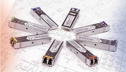








Coarse Wavelength Division Multiplexing (CWDM) is a technology that allows up to 18 independent wavelengths to be transmitted over a single optical fiber. Detailed guidelines are defined in the ITU-T G.694.2 standard, which specifies, among other things, the exact wavelength grid from 1270 nm to 1610 nm in 20 nm steps. We have already partially covered this topic in the article: Passive wavelength-division multiplexing systems.
Here we look more closely at solutions that enable CWDM systems over a single optical fiber (simplex). Some vendors describe their products as Mux/Demux, while others define Mux and Demux as separate devices. What is the difference? And why do only some manufacturers, such as LightOptics, offer both dedicated Mux and dedicated Demux units?
To answer this, we need to look “inside” a CWDM device. Inside you will find a cascade of thin-film filters (Thin Film Filters – TFFs). A TFF is a filter that passes a specific wavelength range and reflects all other wavelengths. The drawing below illustrates this very clearly.
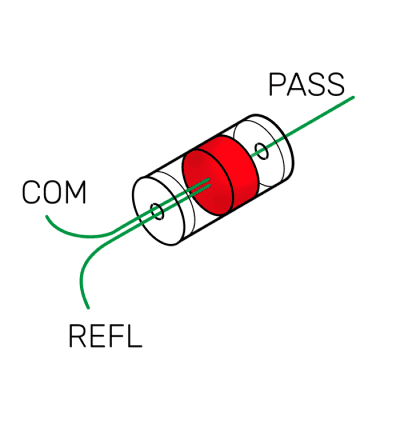
As you can see, the filter has three ports:
• PASS – this port provides the specific wavelength assigned to that filter,
• REFLECTION – this port provides all the remaining wavelengths,
• COM – this port carries the sum of the wavelengths from the REFLECTION and PASS ports.
A very important property of TFFs is that they are “bidirectional”. This means that the same filter can “split” wavelengths that arrive on the COM port into REFLECTION and PASS, and it can also combine what is injected into PASS and REFLECTION onto the COM port.
This is exactly why some vendors name their units Mux/Demux – and, considering what we have just described, this naming is technically correct. If that is the case, why does LightOptics supply two separate products and call them Mux and Demux?
To understand this, a detailed analysis of a single filter is not enough. We have to look at the entire device. Again, we will use a diagram to illustrate this. It shows the internal structure of a CWDM unit – a cascade of TFF filters.
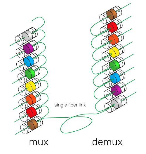
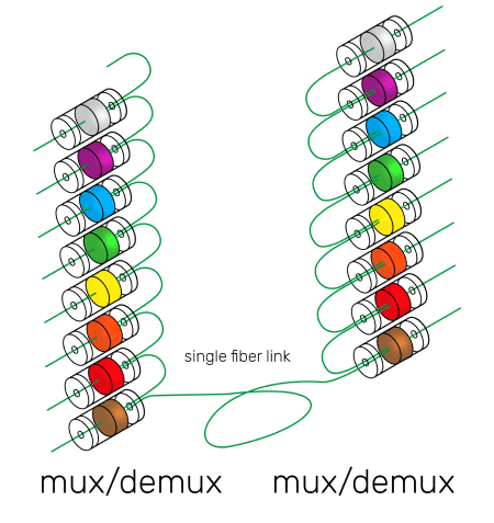
If we extend the filter characteristics with its key parameters, such as insertion loss between COM–REFLECTION and COM–PASS, we arrive at an important conclusion: the further a signal propagates in the filter cascade, the higher the total loss that must be overcome by the wavelength using that position in the chain. For example, insertion loss for channel 2 equals the sum of COM–PASS + COM–REFLECTION, whereas for channel 7 it already equals COM–PASS plus 6 × COM–REFLECTION.
If we assume a point-to-point CWDM link using identical devices at both ends, then the total loss for channel 2 is 2 × COM–PASS + 2 × COM–REFL + the fiber attenuation between them, while for channel 7 it is 2 × COM–PASS + 12 × COM–REFL + the fiber attenuation between them. And what happens when we consider an 18-channel solution?
The difference in attenuation between the first and the last channel can become so high that bringing some channels into operation may be completely impossible.
This is exactly why LightOptics does not offer Mux/Demux units.
Both the Mux and the Demux are built from exactly the same filters; the only difference is the order of the filters in the cascade. This simple change allows the manufacturer to achieve almost identical insertion loss for all channels across the entire CWDM band and therefore significantly reduce the maximum insertion loss of a Mux/Demux pair.
18-channel solutions
CWDM 18-channel optical multiplexer SC/APC 19" rack – model LO-CMS-180-SCA-2761-NR
CWDM 8-channel optical demultiplexer SC/APC 19" rack – model LO-CDS-080-SCA-4761-NR
8-channel solutions
CWDM 8-channel optical demultiplexer SC/APC 19" rack – model LO-CDS-080-SCA-4761-NR
CWDM 8-channel optical multiplexer SC/APC 19" rack – model LO-CMS-080-SCA-4761-NR
4-channel solutions
CWDM 4-channel optical demultiplexer LC/UPC LGX – model LO-CDS-040-LCU-2733-NL
CWDM 4-channel optical multiplexer LC/UPC LGX – model LO-CMS-040-LCU-2733-NL
Do not miss upcoming articles – sign up for the newsletter or follow us on: